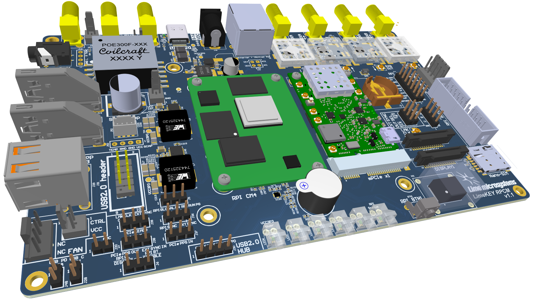
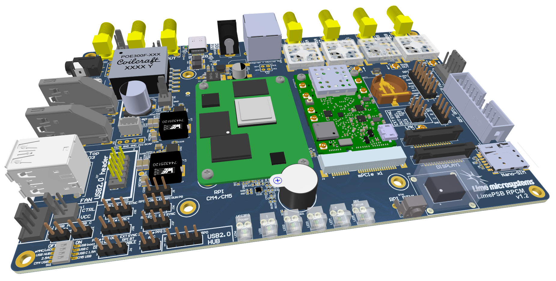
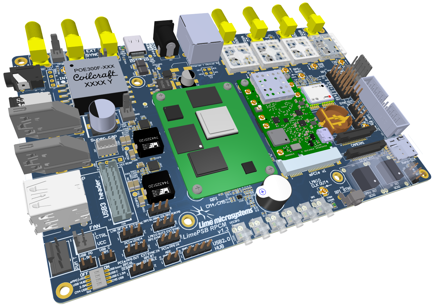
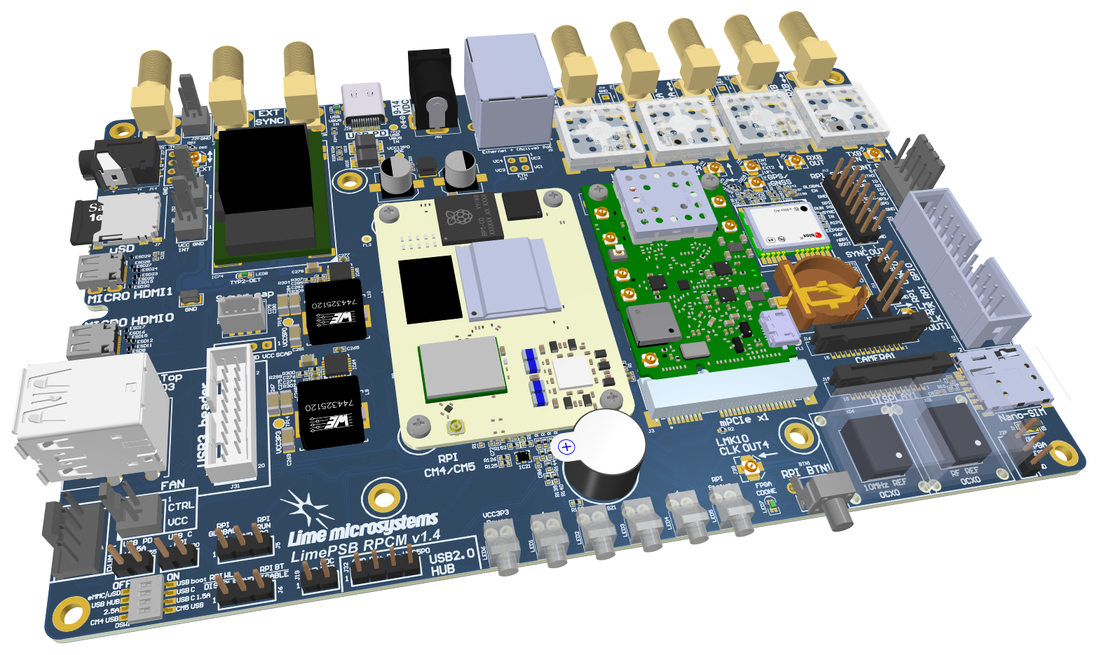
Introduction

LimePSB RPCM Board Key Features

The LimePSB RPCM is carrier board for Raspberry Pi Compute Module 4 (CM4) and mPCIe card (by default LimeSDR XTRX board). LimePSB RPCM carrier board provides a hardware platform for developing and prototyping high-performance designs based on Raspberry Pi CM4, RF front end, clock network and mPCIe card. It allows user to use the board in SDR, LoRa and other applications.

_images/LimePSB-RPCM_v1.1_3D_top.png

Figure 1: LimePSB RPCM v1.0 board top view

_images/LimePSB-RPCM_v1.1_3D_bot.png

Figure 2: LimePSB RPCM v1.0 board bottom view

LimePSB RPCM board features:

  • Connectors:

    • Raspberry CM4 connector (dual row)

    • USB 2.0 (Type-C) socket (USB boot and power delivery)

    • Dual USB 2.0 (type A) socket (downstream ports) or Front Panel USB 2.0 header (unpopulated)

    • Ethernet jack (Gigabit Ethernet with PoE)

    • mini PCIe x1 Gen 2 (5Gbps)

    • 2x HDMI 2.0 receptacle (up to 4Kp60 supported)

    • 2x 15-pin FPC connectors for MIPI DSI display and CSI camera

    • 3.5 mm 4-pin jack for analog audio and composite video

    • uSD card socket

    • Nano-SIM socket

    • Coaxial RF (4x SMA female + 4x U.FL female) connectors for RF front end

    • Coaxial pass-through U.FL to external SMA connector

    • 20-pin Raspberry CM4 GPIO header (3.3V)

    • 14-pin Raspberry CM4 SYS header

    • 5-pin front display connector (power, I2C, button)

    • Raspberry CM4 UART0 header (unpopulated)

    • 2-pin and 4-pin FAN connector (5V default or 3.3V or VCC_INT voltage)

  • RF front end:

    • Configuration: MIMO (2x TRX, 2x RX)

    • LNAs, PAs, RF switches, power and mode control (TDD and FDD)

  • Miscellaneous:

    • Board temperature sensor

    • EEPROM

    • Secure key storage, shift registers

    • RTC, ADC

    • USB 2.0 hub

  • General user inputs/outputs:

    • 4x general purpose Dual colour (RG) LEDs

    • 20 pin CM4 GPIO header (3.3V)

    • Front button

  • Clock system:

    • 30.72MHz (default) on board VCOCXO and 30.72/38.4/40.00MHz (optional) VCTCXOs

    • Possibility to tune on board XO by on-board DAC, by phase detector to match a reference clock input (PTP or external clock).

    • Reference clock/PPS input and output SMA connectors (EXT_SYNC_IN and EXT_SYNC_OUT)

    • Possibility to synchronize multiple boards using coaxial SMA connectors (EXT_SYNC_IN and EXT_SYNC_OUT)

  • Board size: 170mm x 110mm

  • Board power sources:

    • Barrel (9-14V, 2-3A)

    • USB Power Delivery (12V 1.5A or 2.5A)

    • PoE (12V, 2A)

For more information on the following topics, refer to the folowing documents:

Board Overview

The heart of the LimePSB RPCM carrier board is Raspberry PI Compute Module 4 which may be used to transfer digital data between the CM4 and mPCIe board while performing data processing. The block diagram for LimePSB RPCM board is as shown in Figure 3.

_images/LimePSB-RPCM_v1.1_diagrams_r1_block.png

Figure 3: LimePSB RPCM v1.1 board block diagram

LimePSB RPCM board picture with highlighted connectors and main components are presented in Figure 4 and Figure 5.

_images/LimePSB-RPCM_v1.1_top_components.png

Figure 4: LimePSB RPCM v1.1 board top connectors and main components

_images/LimePSB-RPCM_v1.1_bot_components.png

Figure 5: LimePSB RPCM v1.1 board bottom connectors and main components

Description of board components is given in the Table 1.

Table 1. Board components

Miscellaneous devices

IC9

IC

I²C temperature sensor LM75

IC10/IC11

IC

I²C EEPROM Memory 128Kb (16K x 8), connected to RF transceiver I2C bus

IC12/IC13

IC

I²C secure key storage

IC15/IC17

IC

I²C Real time clock

IC8

IC

8 channel 12 bit ADC

IC14, IC16

IC

8 bit shift register

IC19

IC

USB2.0 HUB

IC20

IC

USB switch

J26, J25

Pin header

2-pin and 4-pin FAN connector (5V default or 3.3V or VCC_INT voltage)

Configuration, Status, Setup Elements and GPIOs

LED1, LED2, LED3, LED4

Red-green status LEDs

User defined indication LED

LED5

Red-green status LEDs

Raspberry CM4 status

LED6

Green status LED

Power indication LED

J14

Header

14-pin Raspberry CM4 SYS header

J5

Header

Power control and PG status

J6

Header

Wireless LAN and Bluetooth control

J10

Header

20-pin CM4 GPIO header

RF front end

IC32, IC33

IC

PA SBB-5089

IC36, IC37

IC

LNA SPF5043Z

IC30, IC31, IC34, IC35

IC

RF switch SKY13286

Communication Ports

J1, J2

Connector

Raspberry Pi CM4(L) connectors

J11

Header

Raspberry CM4 UART0 header (unpopulated)

J8

Header

5-pin front screen connector (power, I2C, button)

J27

USB

USB 2.0 (Type-C) socket

J29

USB

Dual USB 2.0 (Type-A) socket

J9

Ethernet

Gigabit RJ45 (Ethernet with magnetics) port

J12, J13

HDMI

HDMI 2.0 socket

J17, J18

LVDS

FPC 15-pin for display and camera

J16

Audio/Video

3.5 mm jack

J7

SDIO

Micro SD card holder

J4

Nano-SIM

Nano-SIM card holder

J3

Mini PCIe

Mini PCIe x1 expansion slot

Clock Circuitry

XO1

VCOCXO

30.72 MHz VCOCXO

XO2

VCTCXO

30.72 MHz VCTCXO

XO3

VCTCXO

30.72 MHz VCTCXO

XO4

VCTCXO

40.00 MHz VCTCXO

XO5

VCTCXO

38.40 MHz VCTCXO

IC27 (IC29)

IC

16 (8) bit DAC for XOs VC tuning

IC25

IC

Clock buffer

IC28

IC

Phase detector

J32

SMA connector

Reference clock input EXT_SYNC_IN

J35

SMA connector

Reference clock output EXT_SYNC_OUT

J33

U.FL connector

Reference clock output

J22/J24, J23

Multiple

Internal connector J22/J24 to external SMA J23

Power Supply

IC45

IC

Switching regulator ADP2386 (3.3V rail)

IC46

IC

Switching regulator ADP2386 (5.0V rail)

IC47

IC

Linear regulator AP7361-FGE (3.3V rail)

IC49

IC

Linear regulator AP7361-FGE (1.5V rail)

IC48

IC

Voltage reference AS431ANTR-G1 (2.5V rail) (unpopulated)